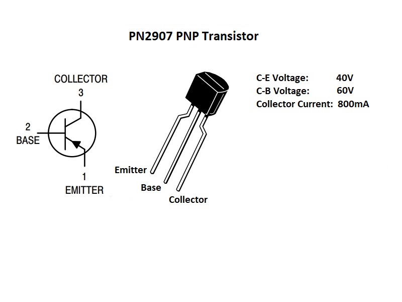

The arrow points in the direction of conventional current so that we know how to connect them into our circuits. Transistors are shown on electrical drawings with symbols like these. In this transistor I’ll place these side by side so you can see how they compare. In this example, when the switch is pressed, there are 25 milliamps flowing into the emitter, 20 milliamps flowing out of the collector, and five milliamps flowing out of the base. If we remove the main circuit, the control circuit Led will still turn on. The rest of the current flows through the transistor and through the main Led and then back to the battery. We can see with this type that some of the current flows out of the base pin and returns to the battery. The main circuit is off until we press the switch on the control circuit. The current therefore combines in this transistor with a PNP transistor, we again have the main circuit and the control circuit, but now the emitter is connected to the positive of the battery.

There are 20 milliamps flowing into the collector pin and 25 milliamps flowing out of the emitter. In this simplified example, when the switch is pressed, there are five milliamps flowing into the base pin. We can remove the main circuit and the control circuit Led will still turn on when the switch is pressed, but the current is returning to the battery through the transistor. On the control circuit we can see the current is flowing through both wires to the transistor. The main circuit is off until we press the switch. Both are connected to the positive of the battery. With an NPN transistor we have the main circuit and the control circuit. The entire thing is enclosed in a resin to protect the internal materials. In a PNP transistor this is just configured the opposite way. The base wire is connected to the P type layer. In an NPN transistor we have two layers of N Type material and one layer of P type. Inside the transistor we have the collector pin and the emitter pin between these. We can sandwich these together to form an NPN or a PNP transistor. We combine these materials to form the PN junction.
PNP TRANSISTOR FREE
Pure Silicon has almost no free electrons, so what engineers do is dope the Silicon with a small amount of another material which changes its electrical properties. So do check the manufacturer’s datasheet. However, not all transistors use this configuration. Typically with these resin body type transistors with the flat edge, the left pin is the emitter, the middle is the base, and the right side is the collector. This stands for the emitter, the base and the collector. Now, with a transistor we have three pins labelled E, B and C.

The two transistors look nearly identical, so we need to cheque the part number to tell which is which. We have two main types of bipolar transistors, the NPN and the PNP type. Scroll to the bottom to watch the YouTube tutorial. What is the difference between an NPN and a PNP transistor. If you like this post probably you might like my next projects, so please support me by subscribing my blog and like my Facebook Page.NPN and PNP transistors explained. Thanks for reading, you can contact me by leaving a comment.


 0 kommentar(er)
